Network Packet Forensic using Wireshark
Today we are going to discuss “Network Packet Forensic” by covering some important track such as how Data is transferring between two nodes, what is “OSI 7 layer model” and how Wireshark stores which layers information when capturing the traffic between two networks.
As we know, to transfer data from one system to another, we need a network connection, which can be wired or wireless. However, the actual transmission of data does not only depend on the network connection; it also involves several phases for transmitting data from one system to another, which the OSI model explains.
OSI stands for Open Systems Interconnection model. This is a conceptual model that defines and standardizes the process of communication between the sender’s and receiver’s system. The data is transfer through 7 layers of architecture where each layer has a specific function in transmitting data over the next layer.
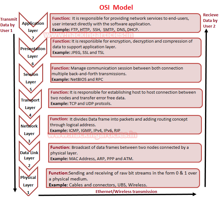
Now have a look over given below image, where we had explained the functionality of each layer in the OSI model. So when the sender’s network transmits data, it goes in a downward direction and moves from the application layer to the physical layer. Whereas, when the receiver receives the transmitted data, it comes in an upward direction from the physical layer to the application layer.
Flow of Data from Sender’s network: Application > Presentation > Session > Transport > Network > Data Link > Physical
Flow of Data from Receiver’s network: Physical > Data Link > Network > Transport > Session > Presentation > Application
Examine Layers captured by Wireshark
Basically when a user opens an application for sending or receiving Data then he directly interacts with the application layer for both operations either sending or receiving of data. For example, we act as a client when use Http protocol for uploading or Downloading a Game. FTP for downloading a File. SSH for accessing the shell of the remote system.
While connecting with any application for sharing data between server and client. We make use of Wireshark for capturing the flow of network traffic stream to examine the OSI model theory through captured traffic.
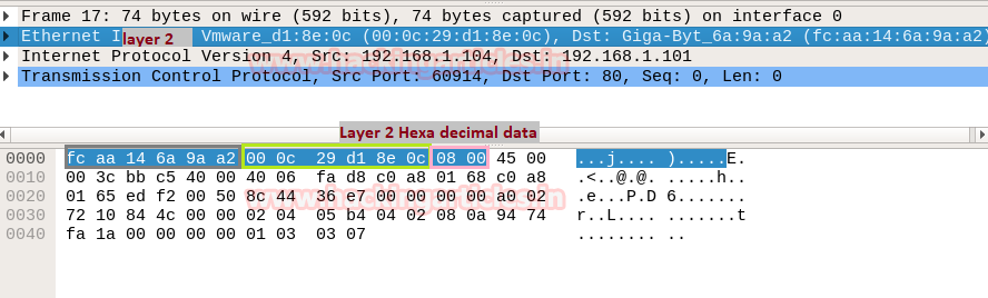
From image given below, you can observe that Wireshark has captured the traffic of four layers in direction of the source (sender) to destination (receiver) network.
Here it has successfully captured Layer 2 > Layer 3 > Layer 4 and then Layer 7 information.

Ethernet Header (Data Link)
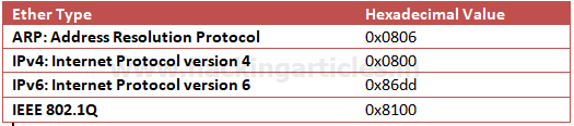
The data link layer holds 6 bytes of the sender’s system and receiver’s system Mac address, and 2 bytes of Ether type indicate which protocol is encapsulated, i.e., IPv4/IPv6 or ARP.
In Wireshark Ethernet II layer represent the information transmitted over the data link layer. From given below image you can observe that highlighted lower part of Wireshark is showing information in Hexadecimal format where the first row holds information of Ethernet headers details.
So here you can get the source and destination Mac address which also available in Ethernet Header.
The row is divided into three columns as described below:

We represent the MAC address of the system in Hexadecimal format, but both types generally categorize in the ways given below :
Once again if you notice the given below image then you can observe the highlighted text in Pink colour is showing hex value 08 00 which indicates that here IPv4 is used.
IP Header (Network Layer)
Wireshark describes the IP header that holds the network layer information, known as the backbone of the OSI model. It contains complete details of Internet Protocol version 4. The network layer divides the data frame into packets and defines their routing path through hardware devices such as routers, bridges, and switches. The network identifies these packets through their logical address, i.e., the source or destination network IP address.
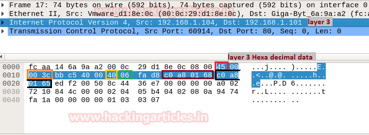
In the image of Wireshark, I highlighted six most important values that contain vital information of a data packet. This information always flows in the same way as it encapsulates in the same pattern for each IP header.
Now here, 45 represent IP header length where “4” indicates IP version 4 and “5” is header length of 5 bits. While 40 is time to live (TTL) of packet and 06 is hex value for TCP protocol. This means these values changes if anything changes i.e. TTL, Ipv4 and Protocol.
Therefore, you can take help of given below table for examining TTL value for the different operating system.

Similarly, you can take help of given below table for examining other Protocol value.

From given below image you can observe Hexadecimal information of the IP header field and using a given table you can study these value to obtain their original value.

The IP header length always represents the bit, and here it shows 5 bytes, which is also the minimum IP header length. To make it 20 bytes, you multiply 4 by 5, resulting in 20 bytes.
TCP Header (Transport Layer)
Transmission Control Protocol (TCP) and User Datagram Protocol (UDP) and Internet Control Message Protocol (ICMP) are the major protocols. They gives host-to-host connectivity at the Transport Layer of the OSI model. We also know it as the Heart of the OSI model because it plays a major role in transmitting error-free data.
By examining Network Layer information through Wireshark, we found that TCP establishes a connection with the destination network.
We knew that a computer communicates with another device like a modem, printer, or network server; it needs to handshake with it to establish a connection.
TCP follows Three-Way-Handshakes as describe below:
- A client sends a TCP packet to the server with the SYN flag
- A server responds to the client request with the SYN and ACK flags set.
- Client completes the connection by sending a packet with the ACK flag set
Structure of TCP segment
Transmission Control Protocol accepts data from a data stream, splits it into chunks, and adds a TCP header creating a TCP segment. A TCP segment only carries the sequence number of the first byte in the segment.
A TCP segment consists of a segment header and a data section. The TCP header contains mandatory fields and an optional extension field.

Different Types of TCP flags
TCP flags control bits specify particular connection states or information about how a packet should be set in TCP headers. TCP flag field in a TCP segment will help us to understand the function and purpose of any packet in the connection.
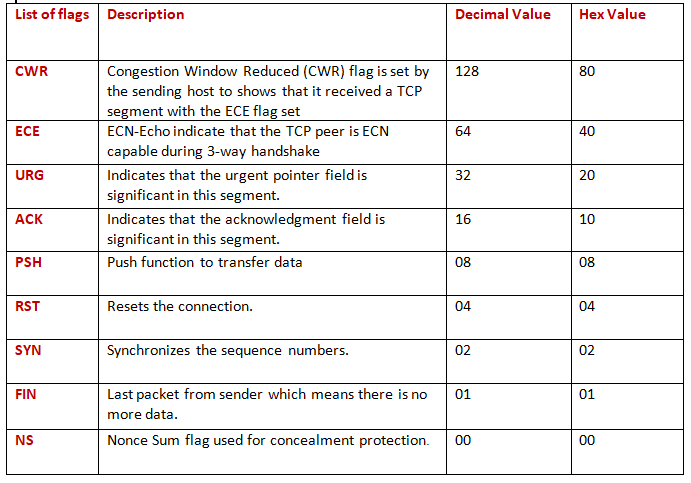
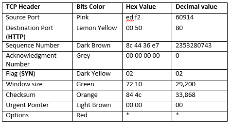
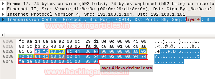
From image given below, you can observe Hexadecimal information of TCP header field. Using the given table you can study these value to obtain their original value.
Sequence and acknowledgment numbers play a major part in TCP. They serve as a way to guarantee that all data transmits consistently. Since, the receiver must acknowledge all data transferred through a TCP connection in a suitable way. When the receiver does not send an acknowledgment, the sender will again send all unacknowledged data.
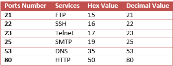
Using given below table you can read Hex value of other Port Number and their Protocol services. Although these services operate after getting acknowledgment from the destination network and explore at application layer OSI model.
In this way, you can examine every layer of Wireshark for Network Packet Forensic.
To learn more about Cyber Forensics. Follow this Link
Author: Yashika Dhir is a passionate Researcher and Technical Writer at Hacking Articles. She is a hacking enthusiast. Contact here
Thank you for any other excellent post. Where else may anybody get that type of
information in such an ideal approach of writing? I have a presentation next week,
and I’m on the look for such information.
Wow! I just came across this website today looking for the exact type of article on Wireshark. I love how in-depth this is and will definitely visit the site more for future research and studies. Thank you so much
It would be interesting if you made a guide to using tshark, grateful for your work
Great Article RAJ!!!!