Forensic Investigation of Ping Command
Introduction:
When we say “ping,” we often are just limiting its definition to checking whether a host is alive or not. In my opinion, while this purpose is correct, its technical details are often ignored. Many network administrators are unable to answer what ping is in details; or how it works. So in this research-based article, I am going to present some points that I didn’t know before starting to read about the topic.
Tools used: Wireshark, command prompt/terminal, https://www.rapidtables.com/convert/number/hex-to-ascii.html
In this article, practicals are based on a Windows 10 x64 system to ping a Debian Linux x64 bit architecture. While this shouldn’t matter in many cases, it matters for a certain part where we calculate TTL and an anomaly case as well. More of that later though. While reading about this topic I learnt tons of new stuff that for me, as a penetration tester, would definitely be useful to understand in-depth how those exploits are working.
Let’s get to the good stuff now.
Table of Content:
- OSI Model
- Ethernet, IP and ICMP protocols
- Ping command and ping packet
- Wireshark and basic filters
- How is a datagram sent to destination host (understanding layers involved using Wireshark)
- Understanding data size in ping
- MTU in IEEE 802.3i
- Fragmentation in ping
- Anomaly in ping
OSI Model:
OSI stands for Open System Interconnection is a reference model that describes how information from a software application in one computer moves through a physical medium to the software application in another computer.
It has seven layers and each layer performs a special network task. They are as follows:

Each layer has a specific task to do and we’re not going into depth with each and every one of them. Let’s save that for another day. Let’s focus on layers 1, 2 and 3 for now.
Layer 1, 2 and layer 3 combined are responsible for the effective transmission of ICMP packets.
Ethernet, IP and ICMP Protocols
While “pinging” a system, layers 1, 2 and 3 are in action. Each layer defines its own “format of protocol options” known as a header. It precedes the actual data to be sent and has information such as the source IP, destination IP, checksum, type of protocol etc. And when it is attached with the actual data to be sent, it forms a protocol data unit which is renamed as per the layer.
Default protocol data units (PDU) in these layers are:
- Layer 1: bits
- Layer 2: frame
- Layer 3: packet
- Layer 4: datagram
We’ll be using these terms quite often and it is important to be clear what these terms mean. While the data is travelling through these layers, it is converted virtually into its own PDU.
Ethernet
IEEE 802.3 is a set of standards and protocols that define Ethernet-based networks. Ethernet technologies are primarily used in LANs. There are a number of versions in IEEE 802.3 such as the 802.3a, 802.3i etc. When we ping, there is some data sent to the destination host and in a specific format.
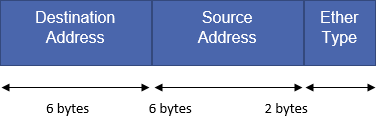
Ethernet header:
IP (Internet Protocol)
It is the principal communications protocol for relaying datagrams across network boundaries. IP has the task of delivering packets from the source to the host solely based on the IP address in the packet headers. IP defines packet structures that encapsulate the data and headers.
ICMP (Internet Control Message Protocol)
Since IP does not have an inbuilt mechanism for error control and sending control messages, ICMP is here to provide that functionality. It is a supporting protocol used by network devices like routers for sending error messages.
Ping
Ping is a computer networking utility used to test the reachability of a host on IP network. Ping operates by sending ICMP Echo request packets and waits for ICMP Echo replies. This reports error, TTL, packet loss etc. One ping request is a combination of Ethernet, IP and ICMP headers and data.
Useful ping options in windows and Linux are:
Windows:
| Options | Functionalities |
| -t | To see statistics and continue – type Control-Break; To stop – type Control-C.
Ping the specified host until stopped. |
| -a | Resolve addresses to hostnames. |
| -n count | The number of echo requests to send. |
| -l size | Send buffer size. |
| -f | Set Don’t Fragment flag in packet (IPv4-only). |
| -i TTL | Time To Live. |
| -v TOS | Type Of Service (IPv4-only. This setting has been deprecated and has no effect on the type of service field in the IP Header). |
| -r count | Record route for count hops (IPv4-only). |
| -s count | Timestamp for count hops (IPv4-only). |
| -j host-list | Loose source route along host-list (IPv4-only). |
| -k host-list | Strict source route along host-list (IPv4-only). |
| -w timeout | Timeout in milliseconds to wait for each reply. |
| -R | Use the routing header to test reverse route also (IPv6-only). Per RFC 5095 the use of this routing header has been deprecated. Some systems may drop echo requests if this header is used. |
| -S srcaddr | Source address to use. |
| -c | Compartment Routing compartment identifier. |
| -p
|
Ping a Hyper-V Network Virtualization provider address. |
| -4 | Force using IPv4. |
| -6 | Force using IPv6. |
Linux:
| Options | Functionalities |
| -a | use audible ping |
| -A | use adaptive ping |
| -B | sticky source address |
| -c <count> | stop after <count> replies |
| -D | print timestamps |
| -d | use SO_DEBUG socket option |
| -f | flood ping |
| -h | print help and exit |
| -I <interface> | either interface name or address |
| -i <interval> | seconds between sending each packet |
| -L | suppress loopback of multicast packets |
| -l <preload> | send <preload> number of packages while waiting replies |
| -m <mark> | tag the packets going out |
| -M <pmtud opt> | define mtu discovery, can be one of <do|dont|want> |
| -n | no dns name resolution
|
| -O | report outstanding replies |
| -p <pattern> | contents of padding byte |
| -q | quiet output |
| -Q <tclass> | use quality of service <tclass> bits |
| -s <size> | use <size> as number of data bytes to be sent |
| -S <size> | use <size> as SO_SNDBUF socket option value |
| -t <ttl> | define time to live |
| -U | print user-to-user latency |
| -v | verbose output |
| -V | print version and exit |
| -w <deadline> | reply wait <deadline> in seconds |
| -W <timeout> | time to wait for response |
IPv4 options:
| Options | Functionalities |
| -4 | use IPv4 |
| -b | allow pinging broadcast |
| -R | record route |
| -T <timestamp> | define timestamp, can be one of <tsonly|tsandaddr|tsprespec> |
IPv6 options:
| Options | Functionalities |
| -6 | use IPv6 |
| -F <flowlabel> | define flow label, default is random |
| -N <nodeinfo opt> | use icmp6 node info query, try <help> as argument |
Ping sends out IP packets with ICMP_Echo_Request to the destination and waits for its reply (IP packet with ICMP_Echo_Reply).
The ICMP packet is encapsulated in an IPv4 packet. The general composition of the IP datagram is as follows:

When a ping command is sent to the host, the datagram is encapsulating Ethernet header, IP header, ICMP header and payload too. The minimum size of an IPv4 header is 20 bytes and the maximum size is 60 bytes.
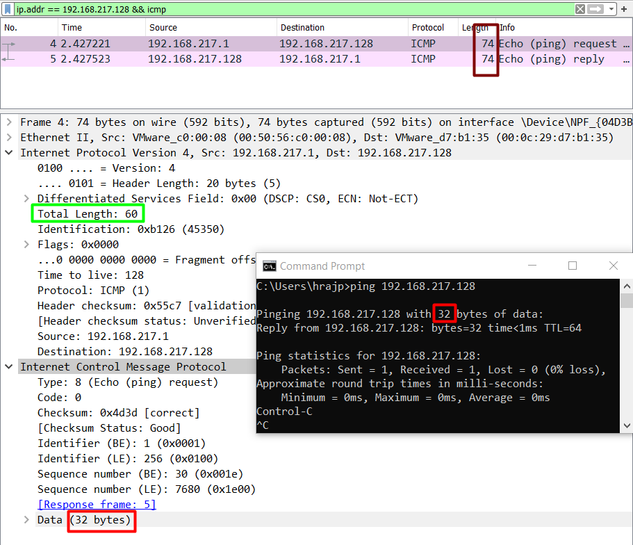
The default size of payload data in ping in windows is 32 bytes. Let’s add 20 bytes of IP header in it and 8 bytes of ICMP header. 32+20+8, it comes out to be 60 bytes.
But, when we analyse ping in Wireshark, the size of the frame written in the log is 74 bytes. This is because while pinging, we would need the destination and source MAC address as well, which is available in the Ethernet header.
So, 14 + 20 + 8 + 32 = 74 bytes.
So, ping sends an encapsulated IP packet which is a combination of:
Ethernet header + IP header + ICMP header + ICMP payload
But, keep on reading for very interesting cases that made me write this article.
Wireshark and Basic Filters
Wireshark is a freely available network monitoring tool that is able to log all the traffic incoming and outgoing from a single NIC card. I won’t be telling how to set up Wireshark and start logging, please use this tutorial for it.
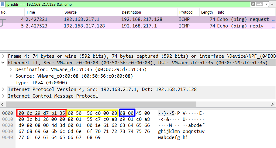
In the above case, when we ping a Linux system from a windows system, we see something like:

Let’s go step by step and see what just happened.
- I’ve pinged IP address 192.168.217.128 from my source IP 192.168.238.1 and captured just one packet to see clearly the action.
- On the top, there is a Wireshark filter applied for the IP address that goes like addr == 192.168.217.128
- Some other useful Wireshark filters are:
http or dns
tcp.port==xxx
tcp.flags.reset==1
tcp contains xxxx
tcp.stream eq X
tcp.seq == x
http.request
udp contains xx:xx:xx
- Next, you can see the total length of the datagram sent, that is, 74 bytes, as already explained above.
- Then you can see, in yellow, Ethernet frame. Here, you’ll find the Ethernet header.
- After that is the IPv4 packet. IP is used to deliver packets from source to destination based on the IP addresses.
- Finally, we see the ICMP header and payload data.
- All these layers are involved in a simple ping over IEEE 802.3. In the next section, we’ll learn how to analyse a packet data using Wireshark to get an in-depth view of packet forensics.
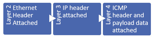
How is a datagram sent to the destination?
When a datagram is sent from source to destination, in our case, when we ping, the format of the datagram is as follows:
We’ll ping a destination with default options:
ping 192.168.217.128
Let’s start analysing the traffic in Wireshark now.
I just captured a single datagram in Wireshark when I pinged a destination host and analysed it layer by layer.
Talking about Layer 2 here, we can see that Ethernet type 2 is being used.
As we talked in point 2, Ethernet frame sent with ping includes the source and destination MAC along with the type of protocol being used.
0000 00 0c 29 d7 b1 35 00 50 56 c0 00 08 08 00
Destination MAC Source MAC EtherType
(6 bytes) (6 bytes) (2 bytes)
The most important field here is the EtherType field as on analysing these bytes we can find the protocol that was used in the communication. This is really essential for forensics point of view and some of the most important hex values are:
| Ethernet Types | Hex Value |
| ARP | 08 06 |
| IPv4 | 08 00 |
| IPv6 | 86 dd |
| IEEE 802.1Q | 81 00 |
Moving on to layer 3, we see an IP packet, since obviously ping is using IP protocol to check if a host is alive or not. Here is the observation of the hex dump of IP packet:
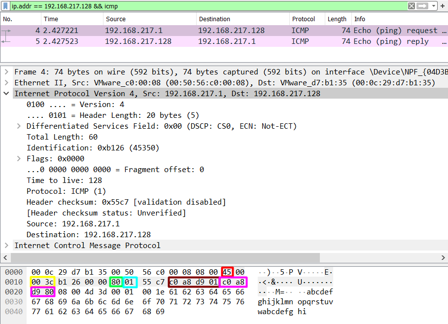
0000 ….45 00 00 3c da 40 00 00 80 01 2c ad c0 a8 d9 01
Header Type Total TTL Protocol Source IP
Length of service Length
(1 byte) (1 byte) (2 bytes) (1 byte) (1 byte) (4 bytes)
0010 c0 a8 d9 80
Destination IP
(4 bytes)
From the analysis of this IP packet, we observe that IP header is then added to the Ethernet frame to make a packet that has the above-mentioned options specified. By analysing this data we can observe a lot of different things. Some of which are:
TTL:
| OS | Hex Value TTL | Decimal Value TTL |
| Windows | 80 | 128 |
| Linux | 40 | 64 |
| Mac | 39 | 57 |
Type Of Protocol:
| Protocol | Hex Value | Decimal Value |
| ICMP | 1 | 1 |
| TCP | 6 | 6 |
| EGP | 8 | 8 |
| UDP | 11 | 11 |
One really interesting thing to note is the Header Length. We see that header length is written as 45 in hex which comes out to be 69 which is not possible. On further breaking down this byte, we see that the first nibble (half byte) tells the version of the protocol.
4 = hex value = 4 (version of protocol), that is IPv4
5 = hex value = IHL (Internet Header Length) = next for bits
And so on (total length = 00 3c = 60 bytes)
A datagram is completed and transported when ICMP header is added in Layer 3. We know that IP lacks error control mechanism, so ping uses ICMP to serve that purpose. ICMP protocol is specified in IP header as we saw above and hence, it is important to analyse ICMP header to better understand the underlying mechanism of ping.

0000 08 00 4d 53 00 01 00 08 61 62 63 64 65 66 67 68
Type Code Checksum Data
(1 byte) (1 byte) (2 bytes) (32 bytes)
0010 69 6a 6b 6c 6d 6e 6f 70 71 72 73 74 75 76 77 61
0020 62 63 64 65 66 67 68 69
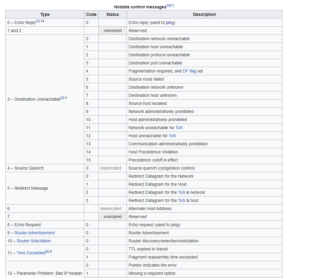
Type: It is the type of request of ICMP request sent. According to IANA, there are 45 assigned requests.

We can see, 08 as the Type of request which symbolises Echo request. When one system pings another system, it sends a Type 8 request and if the host is alive, the host sends back Type 0 (Echo Reply) request.
Code: It is simply the hex value of the type of ICMP request message. It ranges from 0 to 15 for each of the types. This reference is taken from Wikipedia:
Checksum: “The checksum is the 16-bit one’s complement of the one’s complement sum of the ICMP message starting with the ICMP Type. For computing the checksum, the checksum field should be zero. If the total length is odd, the received data is padded with one octet of zeros for computing the checksum. This checksum may be replaced in the future.” – RFC 792
So, to calculate the checksum, we have to split the ICMP header and payload data into multiple pairs of 2 bytes each, calculate the one’s complement of first two bytes, add with the next one and repeat it till all the bytes are exhausted.
Here, checksum status is shown as good and correct, so we need not look any further.
Data: Contains other essential data like timestamp, sequence number, magic number etc.
Data size in ping
According to RFC 791, an IP can handle a datagram of maximum size 65,535 bytes. However, by default, the data in ping is 32 bytes and the whole datagram is by default 60 bytes in case of windows. Adding 14 extra bytes of Ethernet header, it comes out to be 74 bytes which we see in Wireshark. Focus on the colour codes here:
Red= ICMP payload data size
Green= Total length of the IPv4 packet
Maroon= Total length of the datagram
Let’s talk about Linux now. The default IP packet size in Linux’s case is 56 bytes. Adding extra 28 bytes of IP and ICMP header makes it 84 bytes. Adding more 14 Ethernet frame header bytes makes it 98 bytes.
However, we can add data as per our wish, as long as it remains under 65,535 bytes using the ping –l option in Windows. This also has some limitations. Let’s talk about them in the next section.
MTU in IEEE 802.3i
MTU stands for Maximum Transmission Unit and it is the size of the largest Protocol Data Unit that can be communicated in a single network-layer operation. IEEE 802.3 standards restrict the minimum to 48 bytes and the maximum to 1500 bytes. So, if I am to transfer more than 1500 bytes of data in a single datagram, it would be fragmented into multiple packets.
To understand MTU, we’ll take up four cases:
Data payload size=200 bytes, 1472 bytes, 2000 bytes, 65500 bytes
Payload size 200 bytes:
ping –l 200 192.168.217.128
We see that the size of IPv4 datagram comes out to be 242 bytes. This is a result of 200 payload bytes + 8 bytes ICMP header + 20 bytes of IP header + 14 bytes of Ethernet header. The noticeable thing here is that still a single datagram is sent and no fragmentation is done. Let’s push the limit to MTU now.

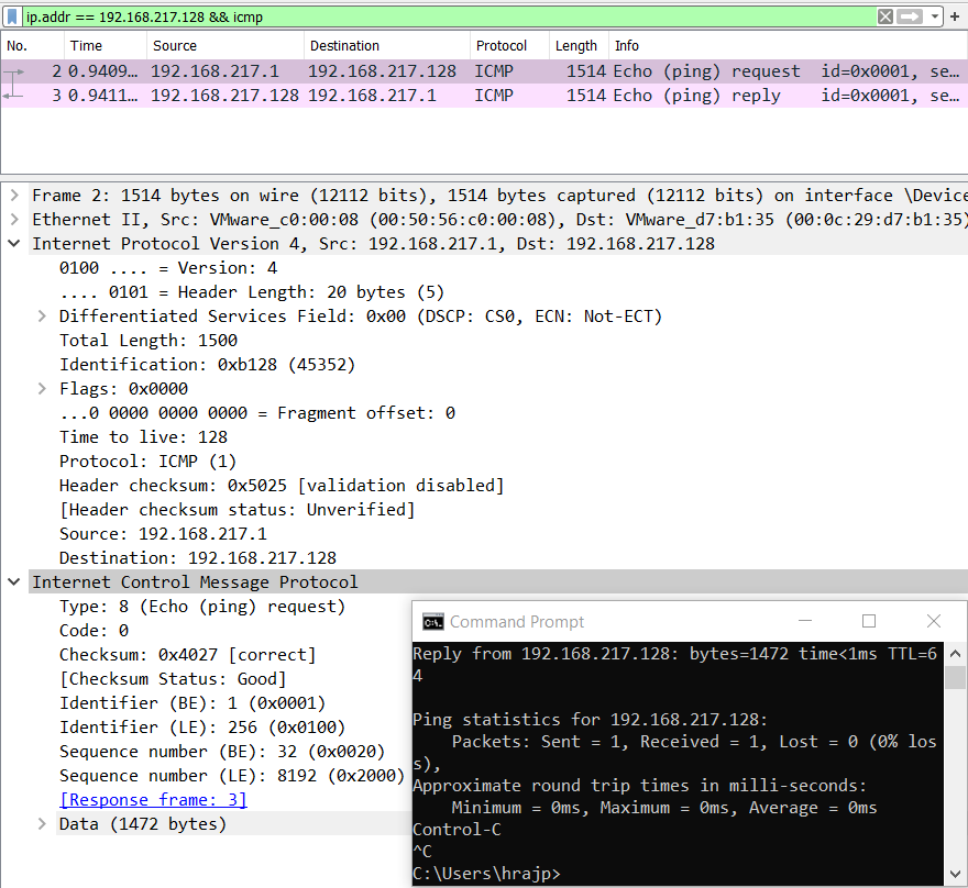
Now let’s push the limits of ping packet to the MTU, that is, 1500 bytes in case of an IEEE 802.3.
ping -l 1472 192.168.217.128
Notice some things here. We have not set the data size as 1500 which is the MTU rather 1472 due to the fact that protocol has some bytes for the headers in reserve.
20 bytes of IP and 8 bytes of ICMP headers are automatically added in every transaction as we’ve seen. So, 1500-28=1472 is the maximum payload data size that we can specify in a ping command.
These 1500 bytes are then collated with ethernet header and finally, a datagram of 1514 bytes is transferred.
So, what will happen when this data size is increased from 1472? Let’s check out.
Fragmentation in ping
IP fragmentation or ping fragmentation is a process in which a packet exceeding the size of MTU is broken into multiple pieces and transacted to the destination host. RFC 791 has the procedure for IP fragmentation, transmission and reassembly of packets.
Let’s increase the size of the data payload to 2000 bytes and let’s see what happens.
ping –l 2000 192.168.217.128
Now, we can see that fragmentation is done and the datagram is split into two fragments of size 1480 and 520 bytes. Why?
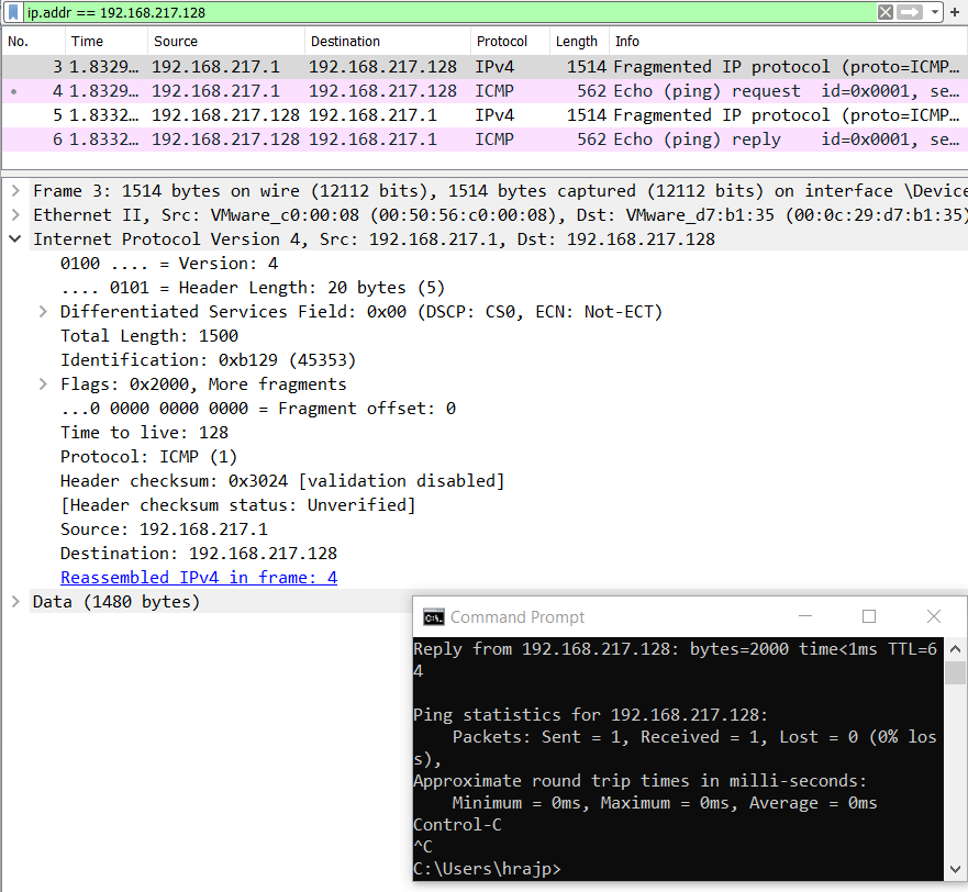
The first fragment is 1500 bytes in total length but the data is only 1480 because 20 bytes are always in reserve for IP protocol header, and the second fragment is 520 bytes in payload data size.
First fragment= 1480 (data size) + 20 (IP header)
Second fragment= 520 (data size) + 20 (IP header) + 8 (ICMP header)
It is important to note that ICMP header is not added in the first fragment and it will only be added when the whole datagram is complete. It is because ICMP is responsible for error control and it calculates the checksum. For checksum to be calculated, whole data should be transmitted first and hence, ICMP header is not added in the initial fragments but only in the last fragment.

Now we push these limits to the maximum size.
ping –l 65500 192.168.217.128
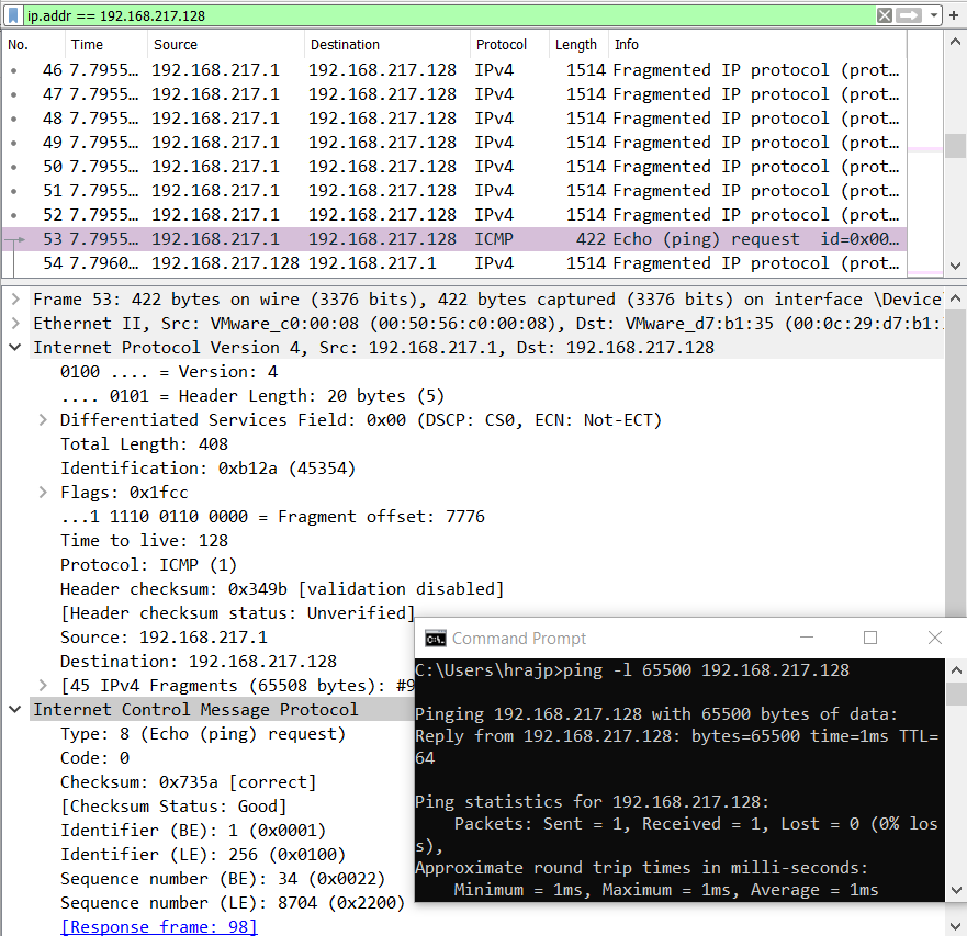
Here, the datagram is split into multiple 44 fragments of 1480 bytes each and the last packet is 408 (minus 28= 380 bytes) bytes in size.
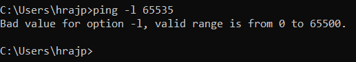
You must not get confused here. 65500 is the maximum size of a payload that we can specify in ping.
However, each of the 44 frames is of size 1500 bytes and the last frame is 388+20+8 bytes, which comes out to be 66416 bytes. Hence, the cumulative size of a packet datagram can be at max 66416 bytes.
Add on extra 14 bytes of Ethernet header, it comes out to be: 67,046 bytes.
Anomaly in Ping
Let’s focus on a case when the payload size is specified as 0. Let’s see what the protocols do with 0 bytes of data.
ping –l 0 192.168.217.128
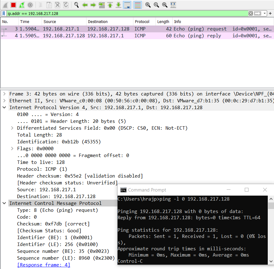
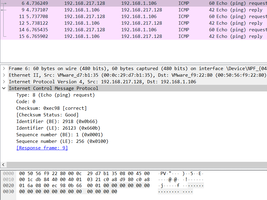
As expected, the request goes with 42 bytes (20 + 8 + 14) with 0 bytes of data but wait, why does the reply come back as 60 bytes?
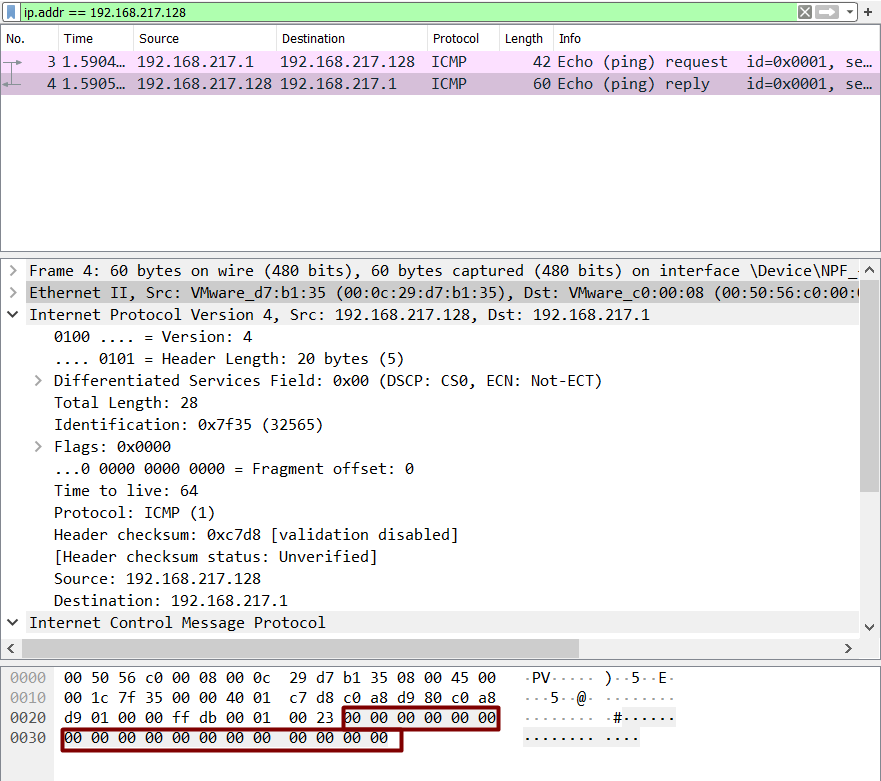
On analysing the hex dump, we see that a Linux system is replying with 18 null bytes of data.
If we specify ping –s 0 in Linux machine, maybe we get some answer.

Okay, so in the terminal, we see “pinging with 0 (28) bytes of data” which means 28 bytes of IP plus ICMP header and 0-byte data. BUT, Wireshark shows us something size of 60 bytes and has again added an extra 18 bytes.
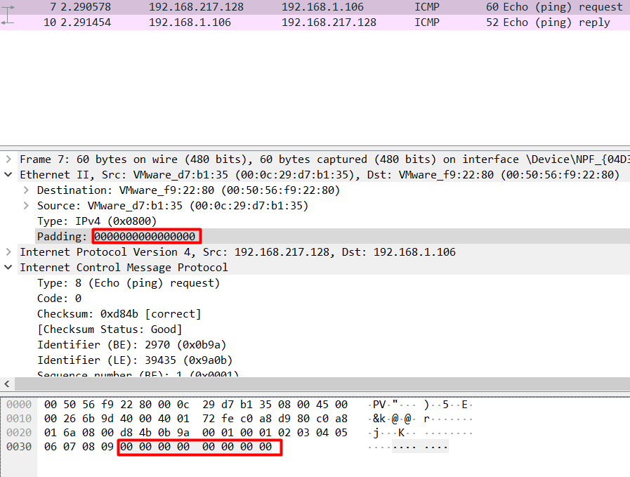
Turns out that these 18 bytes are Ethernet padding bytes and that’s why this anomaly has arisen. IEEE 802.3 adds extra bytes if data is less than 18 bytes in case of Linux known as padding bytes or pad bytes.
Let’s specify a data in the range: 1<x<18 for example, 10 bytes. Let’s see what happens.

In Wireshark, we see the size is still 60 bytes. And 10 bytes have been written by the hex values from 0 to 9, while rest of them are still null bytes.
It is safe to say the same anomaly will exist when we specify data in the multiples of 1480 since the last fragment will have 0 bytes of data to be sent and padding would be added.
This was an interesting anomaly and made us understood some details of the IEEE 802.3 standards difference in Windows and Linux.
Author: Harshit Rajpal is an InfoSec researcher and left and right brain thinker. contact here
Good info
Amazing
Great research efforts very helpful for forensic perspective
Good one. Thanks Hackingarticles.
Awesome ?